
The Pro-Tools HMP 200 tubing bender plans are available for free from Pro-Tools. The dies for this bender can be purchased here.
There are several builds documented online using these plans. The value my post holds is that my bender was built entirely in my garage with equipment I own. I did not build it in a machine shop or a even a well equipped home shop. The materials used were all purchased online, not through a commercial shop. Neither were the materials free commercial shop scrap. If you want to build a tubing bender and are not sure what tools you need or where to get the materials, this post will help you out.
There are some benders you can buy that are cheaper than the build price of this one. You can find benders made by JD Squared here and Pro-Tools here.
I used 1″x5″ hot roll steel for the Base Plate. The material was supposed to be 1018 cold roll 1.5″ thick, but that was not available at Online Metals so I substituted. I cut the plate roughly 1/8″ long to allow for the inadequacies of the band saw.

Sawing Base Plate
I clamped the plate edge up in a vice to mill the ends flat and cut the length down to 7.000″

Machined Base Plate
I clamped the plate again directly to the milling table to get all the height possible beneath the spindle. I drilled the bolt holes in the edge of the plate using collets to hold the drill bits (again for added height beneath the spindle). I tapped the holes in place using a dead center in an R8-MT2 adapter to hold the tap true.

Drilling Base Plate
The Die Wrist Pin Sleeve like the base plate requires its length to be precisely 7.000″. After a rough cut in a band saw I finished the ends with a milling machine.

Facing Die Wrist Pin Sleeve
The 1″ bolt did not slide easily into the Die Wrist Pin Sleeve. The Die Wrist Pin Sleeve is a piece of DOM tubing with an inner diameter of 1″. I used an adjustable reamer clamped in a bench vice to ream out the DOM. I used a pipe wrench to rotate the tubing about the reamer.

Reaming Die Wrist Pin Sleeve
The Side Brackets are toward the upper limit (in length) of what can be easily machined on a 6×26 milling machine. The Side Brackets were shortened by 0.5″, compared to the Pro-Tools drawing to account for the Base Plate being 0.5″ thinner than called for. Since the bracket is shortened, all holes need to be measured with respect to the top except the holes for the base. I did not slot the holes for the base as the drawing showed. I drilled them exact at 0.5″ from the Side Bracket Bottom. I machined the plates clamped together to save set up and machining time. I also did this to improve the accuracy of holes lining up. The holes for the Base Plate attachment and the tapped holes that hold the springs were drilled in one setup. I machined the Die Wrist Pin holes and Roller Pin slot in another setup.

Drilling holes in the Side Brackets for the Base Plate
Below is an example of tapping with a dead center in a milling machine. Using this setup for tapping holes ensures the tap is perfectly aligned with the hole. I used a quill lever to feed the tap in order to avoid avoid using too much pressure.

Tapping hole in Side Brackets
The Side Brackets were clamped to the table using 1/8″ parallels as spacers. I used spacers so I would not drill into the mill table. Two narrow parallels were clamped on top of two wider parallels (wider ones used as spacers). I used a small machinist’s square to line up the parallels before I clamped them to the table. This method worked fairly well for squaring the Side Plates to the table, although I think it was off a few thousandths over 16″. Since the holes for the Base Plate were not slotted, it is important for the Side Plate to be square with the mill table. If the Base Plate Holes are not perpendicular with the Roller Pin slot and Die Wrist Pin Holes, the Hydraulic Jack would not line up correctly. If the jack is not lined up correctly, either due to machining set up error or the Hydraulic Jack cylinder not being normal to the Jack’s base plate, then the Jack’s base plate may be shimmed to account for the error.

Squaring the Side Brackets to the table
I used a center finder to locate the center-punched hole. Centering the Side Plate is not that critical, an error of 0.010″ or maybe more would have been acceptable. Having the holes and slot co-linear is important to reduce side loading on the Die Wrist Pin and Roller Pin.

Aligning the center line of the Side Brackets
Center drill -> 1/8″ bit -> 1/4″ bit -> 1/2″ bit -> 0.975″ 2 flute end mill was used to drill the holes and ends of the slot.

Drilling 0.975″ holes with an endmill
The slot was completed in several passes with a 2 flute 0.975″ end mill.

Cutting a 0.975″ slot
The Die Wrist Pin holes were finished with a boring head. The Die Wrist Pin (1″ bolt) has a different diameter for the shank and the threaded portion, so each Side Plate received a different hole diameter. The smaller diameter was bored in all the Die Wrist Pin holes, then the larger diameter was bored through only one of the two Side Plates. The slot ends were bored to the exact diameter of the Roller Pin (which is a 1″ CR steel rod). Two intermediate areas of the slot were also bored to the final size to give a visual indication of when the slot width was reached. I used a 1/2″ end mill to widen the slot to the final width.

Boring holes
The Side Plate bottoms were squared with an end mill. A small machinists square was used to line up the Side Plates perpendicular to the mill table. This setup was used only because the milling machine lacked the necessary Y-axis travel.

Squaring the bottom of the Side Brackets
I replaced the Stabilizer Tubes list in the HMP-200 plan with threaded rod and nuts. I had seen this done on another build and it seemed to reduce the complexity slightly. The only extra step is the threaded rod stabilizers must be adjusted carefully with an inside caliper to achieve 7.000″ exactly. The Roller Pin was cut to size on a band saw and faced on a lathe. The Roller Pin length dimension is not critical. The Roller Pin holes were drilled using a lathe and the holes taped while chucked in the lathe. The radiused ends of the Side Plates was done by hand with and end mill which is why it is sloppy looking. Using a rotary table would have been a better method of radiusing the ends.

Structure assembled
The Roller was cut from a 2.5″ CR steel rod. Using 2.5″ tubing with 0.75″ wall would have been ideal, but it was difficult to obtain. The rod was cut to a length such that it could be chucked full depth in the 4 jaw chuck with 3.5″ protruding. A 4 jaw chuck was used to more accurately center the piece. The Roller was drilled with a center drill -> 1/8″ bit -> 1/4″ bit -> 1/2″ bit -> 3/4″ MT2 shank bit. The remaining diameter was bored with a carbide insert boring bar to 1.125″. After the hole was bored the roller was faced and outer diameter turned down a few thousandths to be concentric with the bore and also to improve the surface finish. The Roller was cut to length on a band saw then the cut side was faced in a lathe. A bronze sleeve bearing was inserted into the Roller.

Drilling Roller
The Roller Block was the most difficult part to make due to its geometry. The rough cut Block was squared on both sides.

Machining Roller Block square
Multiple holes were drilled in the block to cut out the center of the block.

Roller Block with center drilled out
I used a band saw to cut the sides of the Block; however, the cuts were not complete due to the blade angle.

Cutting Roller Block sides
The finishing cuts were done with a hacksaw. After the scrap piece was removed a fly cutter was used to finish the bottom of the of the channel.

Finishing Roller Block side cut
The Pro-Tools plans were abandoned for boring the bottom of the Roller Block. The hole has two diameters; the larger diameter for the Hydraulic Jack cylinder and the smaller diameter for the screw-out jack extension. The tolerance was made as tight as possible to reduce the play of the Block attached to the Jack.

Boring hole for bottle jack

Finished hole
The Roller Pin hole was drilled in two different setups, but the boring was done in one setup.

Boring holes for Roller Pin
I did not have any means to bend 0.25″ x 4″ CR steel 90 degrees to create the Support Bracket. One piece of the Bracket was slotted with a milling machine before the two pieces were welded together.

Support Bracket clamped for welding
I TIG welded the Support Bracket.

Welded Support Bracket
The completed assembly turned out well.

Assembled Rear

Assembled Front
Materials:
(1) 20 Ton hydraulic Bottle Jack purchased from Harbor Freight. ($39.99)
(4) 1/2″-20 x 1″ grade 8 hex bolts purchased locally from Ace Hardware.
(4) 3/8″-16 x 1.25″ no grade hex bolts purchased locally from Ace Hardware.
(2) 3/8″-16 x 3/4″ no grade hex bolts purchased locally from Ace Hardware.
(4) 3/8″-16 hex nuts purchased locally from Ace Hardware.
(10) McMaster-Carr Materials (see image). ($54.43)
(7) Online Metals Materials (see image). ($214.52)
Total: $308.94 (note this is before shipping or tax and omitting the bolts and nuts that may be purchased locally)

McMaser-Carr Materials

Online Metals Materials
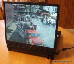
Turning a laptop into a digital picture frame is a pretty common project on the internet. When I searched for examples I found the “cheap and easy” examples were not cheap or easy enough. My response is to make my own Extra Cheap and Extra Easy digital picture frame.
The donor laptop has a 15″ screen, Pentium II 333 mHz processor, 128 mB ram, and was made in 1998…..Extra Cheap.
Some projects suggest ordering a custom picture frame to mount the laptop screen in so it can be hung on a wall. I reversed the laptop screen and left the rest of the laptop unmodified. Reversing the screen works well for placing the photo frame on an end table or shelf. The reversed screen hides the laptop body and keyboard somewhat while giving the screen some angle adjustment. This old laptop screen has a narrow viewing angle so angle adjustment is critical.

Laptop with screen reversed
This LCD screen had two connectors, signal and power. The LCD has to be removed from the screen assembly because the signal cable is taped to the back of the LCD. I re-taped the cable at an angle that will exit the cable near it’s mating connector when the screen is reversed, then re-assembled the screen.
The larger connector on the left is the signal and the smaller one is the power. There is a notch cut into the bottom of the screen assembly to give the LCD power cable a convenient exit when the screen is reversed.

LCD connectors
Using a pocket knife I crudely notched some of the plastic to re-route the cables. All plastic notches are visible in the picture below.

Bezel notched
The keyboard bezel was notched for the LCD signal cable and a plastic window was removed to allow the LCD power cable to pass through.

Bezel notched and window removed
The plastic LCD case was notched to allow the signal cable to pass by without interfering with the hinge or getting pinched.

Notched around hinge
Since the computer has a tiny hard drive ( I think the motherboard is firmware limited to supporting only a few gigabytes) the pictures are loaded through a USB flash drive.
I wanted to use an google picasa online albums in the screen saver, but the wireless cards I tried took up too many system resources. The screen saver is set to automatically display pictures from the flash drive. The computer is set to hibernate after 2 hours to save power.

Screen saver settings
The end result is a device that will power on and start displaying pictures autonomously with only one button press.
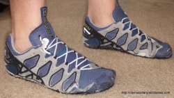
I made these minimalist shoes for about $15 using locally available materials.
I am interested in trying out barefoot running, but the streets around my house are pretty dirty, its getting cold out, and I dont want to invest $50 in Zem O2 shoes (although I may still buy them sometime). Luckily I saved some old running shoes that became worn out in 2006 that I guess I though would become useful sometime in the future? Well the future is now and I have converted my old Solomon running shoes into barefoot running shoes.
Materials:
- Running shoes – free
- Baler Belting – $9.99
- SHOE GOO® – $5.49

Donor Shoes
The original Solomon soles were worn completley through and starting to delaminate from the shoe upper. I was able to rip one sole off with only my bare hands and the second I used a little help from a flat razor blade. The razor blade was also useful in cleaning up the foam still stuck to the sides of the shoes. I made sure to use a new sharp razor blade; that shoe foam is tough to cut. Your hands will be sore after pulling the sole off.

Soles Removed
The shoes have some extra heel support. The suport is a plastic heel cup that is glued between the outer heel fabric and the inner heel fabric. In this particular shoe I was able to work my fingers between the heel cup and the fabric to pull apart the glue bond. I pulled apart as much as I could then put the shoes in the washing machine and washed with hot water. The hot water loosens the glue making it easier to pull out the heel cup. Pulling the heel cup out is VERY difficult and requires a lot of working around the inside of the show with your hands. An alternate way to remove the heel cup is to cut the shoe where it meets the ankle, remove the heel cup, then sew it back together.

Removing Heel Cup
The laces and insoles were removed as well.

Waste Pieces
The Solomon shoes are good donors because they have a leather piece sewn around the whole toe to make the shoe more durable. Other runnings shoes have only mesh on the toe which develops holes by the time the runing shoe wears out. The toe leather on these shoes was completely worn out, but the mesh beneath was in very good shape.
The leather at the front and sides of the shoe does provide some support and shapes the shoe, so that will need to be removed. The stitching can be cut easiest with a flat razor blade in. A seam ripper will also work, but it is much slower. The front part of the shoe must be separated from the bottom to fully remove the leather on the toe. The shoe’s bottom stitches come out easeier with a seam ripper than with a razor blade.

Leather Toe Partially Removed
After all that I have a shoe upper with only mesh fabric on the bottom. The shape of the standard shoe is wrong for comfortable footwear. Most shoes have a pointy toe when the human foot is blunt.

Making the Narrow Shoes Wider
Everybody’s feet are different, so now I took the opportunity widen the foot box and shape the shoe to closely fit my foot. The shoe must be marked, cut, then sewn back together. I use a high quality 100% polyester thread to sew the shoe back up. Sewing by hand with a blanket stitch is probably the easiest method. After the shoe is sewn back together I have a perfectly fitting bootie that conforms to my foot.

New Shape Pinned

New Shape Sewn

Complete Shoes... Sans Soles
Other minimalist shoe and sandal projects on the internet use Vibram Cherry as a soling material. I chose not to use it because it was more expensive and seemed harder to buy in a small quantity and I didnt want to wait for shipping. Luckliy the internet offered a different suggestion for soleing. I used baler belting purchased at tractor supply. To size how much you need put your foot on a piece of paper and spread your toes out as wide as possible then trace your foot, you need double that amount. I used about 24″ of 7″ wide belting. If i had been frugal with the belting I could have used 12″ of 10″ wide belting to make the two soles.

Rough Sizing the Soles

Trimming the Soles
The baler belting is probalby heavier than the Vibram (its pretty heavy). The belting is 4mm thick. I used coarse sandpaper to rough up the side of the sole that is contacting the foot to prep the sole for gluing . After roughing up the soles I scrubbed them with a stiff scrub brush and dish soap. I rinsed, then soaked the soles in water between scrubbings. I scrubbed 3 times then let the soles fully dry before gluing.
The soles are glued with SHOE GOO®. I had intended to make an inside clamping plate out of 1″ pine board cut to the size of the sole then placed inside the shoe to clamp the shoe to a bottom board with C-clamps. I could not do the clamping I wanted because my scroll saw is broken, so I used an inferior clamping method. Since I could not make an insert for the inside clamping surface I used my foot to position the shoe on the sole. I wrapped my foot in plastic wrap in case any of the glue bled through the fabric.

Ready for Gluing
I covered the board with plastic wrap so I would not accidentally glue the soles to the wood. I used some vee blocks, R-8 shanks, and steel cut-offs to hold the shoe to the sole.

Soles in Place
The SHOE GOO® packaging states that the product’s temperature range is 50°F-90°F. I used a heater to bring the temperature of the glue up to 50°F. Using a heater is not ideal and potentially unsafe due to the SHOE GOO® being flammable. The vapor is also harmful and this product should not be used indoors.

Bringing the Glue up to Temperature
I am surprised this stand did not fall over. It is a cardboard tube balanced on a jack stand.

Makeshift Stand
The sole attachment worked well. The soles were still a little large for the shoe so I trimmed off the excess with shears and a razor blade.

Soles Attached
I replaced the original shoe laces with shock cord to obtain a more snug fit.

Shock Cord Laces

Decent Pliability
The finished shoes look pretty good. They almost look better than before the modifications.

Done!
The inside of the shoes was lumpy after gluing on the sole. The bottom shoe fabric bunched and glue bubbles formed. If I had two flat clamping surfaces this would have been avoided. I cut out the lumps from inside the shoe with a flat razor blade and an X-ACTO™ knife with a rounded blade.
These barefoot shoes cost much less than the alternatives and will draw less attention in public.
I was inspired to make my own minimalist shoes partly by this blog post.
Ingredients:
- 1 Avocado
- 1 English cucumber
- 1/4 lb Salmon
- Sushi rice (1 cup sushi rice, 2 tbsp rice vinegar, 1 tbsp sugar, 1 tsp salt)
- Seaweed wraps
- Sushi mat

Specialty Ingredients

Ingredients layout
- Make sushi rice and put into a mixing bowl.
- Mix in vinegar, sugar, and salt with the rice.
- Add water to rice to control the stickiness.
- Slice the cucumber, avocado, and salmon as pictured and set aside.
- Wrap the sushi mat in plastic wrap to avoid getting it dirty.
- Place a seaweed wrap on the sushi mat and cover it with a thin coating of rice. The rice can be spread with a spoon and your fingers. Use a bowl of water to wash the stickiness from your spoon and hands to make spreading easier.
- Place the ingredients on the wrap as pictured.
- Roll the sushi with the mat. If you roll it too tight the insides will squish out the side. If rolled too loosely there are visible voids in the roll when cut.

Ready to roll

Rolling the Sushi
The result is some pretty good sushi.

Done!

Strong Hand© Tools has some very nice welding tables and clamps, and if I were anything close to a professional I would consider buying them…but for the little welding and fabricating I do I cannot justify buying one.
My goal was to make a welding table that I could attach clamps and jigs and fixture parts and assemblies on. I originally wanted to be able to fixture bicycle frames on it, but now I think a specific table and jig should be used for that.
All the professional tables I liked were cast iron, very flat, and had an array of holes for fixturing. Since buying a large piece of flat cast iron or even steel is very expensive I decided to use an existing table and modify it. Some table saws have a cast iron table that is machined flat and thick enough to tap holes into, so I needed a donor table saw.
The table saw I found was a 1960’s Yates American J-Line cabinet saw. The saw came without a fence, but otherwise complete. It even came with a working motor. The saw was a pretty solid design, and I almost felt bad turning it into a welding table. The table is full sized (22″x28″), about 1/4″ cast iron with ribbed supports and it came with 4 cast iron partial table extensions (the shorter 2 are pictured below).

Table top structural ribs.

Table saw with the top cleaned up.
The first thing I did was remove the rust and burs from the table.
I used razor blades as scrapers and some Phosphoric acid based rust dissolver for the rust.
I used some small diamond files to take down the table’s burs.
The table top was measured and drawn in CAD using Google SketchUp. I drew the table out to determine the hole spacing and location. A precise drawing was needed for the table top because I wanted the hole spacing as uniform as possible while still avoiding the support ribs.
I installed a 4″ bench vice on the corner of the table because I figured every welding table needs a vice, I also did not have another bench that I could put the vice on.
I drilled and tapped about 130 holes in the top of the table. Every hole was drilled with a 1/8″ pilot hole, then a 5/16″ minor diameter hole, then tapped with a 3/8″ x 24 tpi tap. All 3 of these operations were performed with a guide block so they would run straight. The tap was only started in the guide block then removed to finish the hole. The tapped holes match the clamping set that I use on my milling machine. Making all those tapped holes took a really really long time. If I was going to make another table like this I would drill the holes with a 20″ drill press or large milling machine and try to power tap them.

Drilling and tapping guide block.
After all the holes were drilled and tapped there was a slight lip on the holes where the tap had pulled up the metal a bit. I used a HSS lathe tool to chamfer the holes by hand so the table would be flat again.

Completed welding table top.

Threaded stud for use with milling clamps.

Bench vises with the bottoms milled flat.
The table extensions could be used as either table extensions or clamped to the table surface and used as a vertical fixturing surface.
The table came out very well. It was invaluable in the Art Cart project.
Future enhancements for the table include building a rolling steel base made out of square tubing, adding a second table top for added area, and modifying some clamps to be used directly with the table.
Watch the race and build VIDEO John made.
On the morning of the derby there were a few things left to do.
1. Attach the rear cowling to the vehicle
2. Fix the steering so it will not go unstable at higher speeds
3. Affix the decals to the vehicle
4. Load and transport across town
I attached the rear cowling as fast as possible, while making sure that the rear wheel was not rubbing on it. I messed with the toe in/out of the steering some, but was not able to completely stabilize the steering. Luckily it was a very low speed course and the steering did not oscillate. The original plan was to stencil and paint on the decals, but with limited time computer printouts and tape were used. The art cart fit in the car perfectly with all wheels attached.


The finished cart looks pretty good. Unfortunately it did not end up looking like a train as intended, but rather kind of like a Ferrari 375 F1.


The full team shown, also the “Fastest Art Cart” trophy.
Breakdown of hours/tasks (from memory, so not 100% accurate.
9-16—–Front wheel pivot assembly—–3h
9-20—–Front wheel pivot assembly—–5h
9-21—–Front brake selection—–1h
9-22—–Front wheel pivot assembly—–3h
9-24—–Box frame—–8h
9-30—–Box frame modification and rear wheel attachment—–7h
10-01—–Front wheel attachment—–8h
10-02—–Front wheel attachment and steering assembly—–9h
10-03—–Greased bearings, polished steering, misc.—–4h
10-05—–Welding chassis—–7h
10-06—–Welding chassis, brakes, steering adjustment, downhill testing —–5h
10-07—–Body and paint—–7h
10-08—–Body, decals—–3h
Finished at 1:30 pm for an event that started at 2:00pm
Approximate total hours: 70
Future plans include fixing the steering (no matter what it takes). Making a proper seat. Installing a rear brake. Performing a speed test up to at least 30 mph. Measuring the weight of the final vehicle.
Extra ambitions plans include sanding and fiber-glassing all edges of the body and installing a 0.75-1.5 HP electric motor.
Watch the race and build VIDEO John made.


Any extra metal had to be cut or ground off. The frame was then fully welded. I used one 60 cu ft argon tank and still had 3 or 4 welds left to go.

Two road bicycle brakes were sued on the front wheels. The cables from the two brakes were clamped together at the steering column where some cable stop braze-on’s were attached. The single brake lever worked well controlling two brakes, but did need considerable force applied to it.
The seat is minimalist. It is a scrap of plywood I found that happened to be a size that would fit between the two frame rails; I didn’t even bother to bolt it to the frame. The seat is much more comfortable than in looks.


The cart is mechanically complete and only lacks a plywood skin. We did a fair amount of testing and found that it performed very well. There were some continuing issues with the steering becoming unstable at high speeds. In the future I may try to give the wheels some negative camber and toe out to increase stability and steering performance.


The front wheel assemblies have been clamped to the chassis. The cart was tested by rolling it around to see how the steering reacted. When rolled forward the steering was stable at low speed, but started to oscillate at higher speed. The steering geometry worked well going forward; if one wheel was steered the opposite wheel mimicked it without being tied together with tie rods. In reverse the steering was completely unstable and the wheels would immediately point toward each other and the cart would stop.


I set the ackermann steering geometry with bicycle stems(steering arms) set inside the headset(kingpin). Temporary tie rods were clamped together to test the steering again. A bell crank method was used to permanently connect the tie rods to the steering column.

A headset was welded to the front of the chassis to use as a bearing for the steering column.

An 0.050 piece of tubing was welded to the steering tube of a bicycle fork to make the steering column. 

Steering column in installed here withe the steering wheel attached. The angle iron frame flexed so much I later had to add another support for the steering column near the steering wheel. The steering wheel is made from a 1″ threadless stem, and cut down handlebar and two bar ends all clamped together.
Mounting the wheels was the most important and difficult task.
My original design had called for a 4 wheel vehicle with the rear wheels being attached with bicycle rear triangles welded to the box frame. I scrapped the 4 wheel plan because it was going to be difficult to mount the rear triangles to the frame. Aligning 2 rear wheels is more difficult than one, and also if the chassis has some twist or the wheels are slightly different heights the cart would have an uneven weight distribution between the wheels. I decided to go with a reverse tricycle 3 wheel design. With this design I was able to shorten the wheelbase by almost a foot, make the rear wheel mounting much easier, and end up with a sleeker more aerodynamic vehicle. The only hit I took was having to add 3 new rear frame members and cut the old rear of the frame off. It worked out well with the new rear frame members being a natural seat back.

Cart shown with the rear wheel tacked and the front wheels mocked in their future location.

Vehicle ground clearance is four 2×4’s.

I was worried the rear triangle attached only to the center frame member would not be strong enough, but this attachment and the whole art cart was much much stronger than I imagined it would be.

The most challenging assembly to fixture was the front wheels. I tacked some re-bar to the frame where I wanted the front wheel axles to be. The re-bar fit right in the front wheel drop-outs. I used the table extension pieces from the table saw to clamp the re-bar parallel to the table and clamp the front fork in the correct position relative to the re-bar. I also had to make sure the front fork was angled 45 degrees forward as planned.

It was a challenge maneuvering around the assembly in the garage.


The tubing supports were notched and fitted to pieces of flat stock so the wheel assembly would be separate from the frame.

The two headset king pins were different lengths and slightly different angles (due to error) so the tubes on either side had to be notched differently. The notching was done on the lathe by rough measuring and trial and error. Angling the tubing to attach to the flat stock was done with a hack saw and a lot of grinding.


The one wheel was looking pretty good, so I decided to put the other one on.


The second front wheel took a little more than half the time of the first one. Finding a clamping method that worked had taken a while with the first wheel. I was also a little less pick about how well the tubing fit up on the second front wheel. You can see I used masking tape to hold the tubing in place while I tack welded it (the tape worked well).
The rolling chassis is complete and ready for testing.
The chassis is made from two old bed frames and some angle iron originally intended for another project. The goal of the day was to make a rectangular cube big enough to fit someone inside.

All of angle iron cuts were made using the cheapest metal cutting band saw ever made (pictured above).

A pile of nicely cut steel ready to be tack welded together.

It was much easier to carry the welding table outside than to work in the tiny garage. A framing square and some clamps did a nice job of squaring up the top and bottom of the frame. One of the corners was 1/8″ off, but that was due to a bad setup on my part. 1/8″ is not bad for a project like this.

First ride in the art cart…it did not move very fast.

Using several clamp in a precarious manor the frame came to form. I very carefully got in to make sure it was big enough to comfortable fit.


The frame was clamped together on a flat piece of concrete sidewalk to keep it square.


Lots of locking pliers and clamps. The frame was tacked together in time for dinner.
